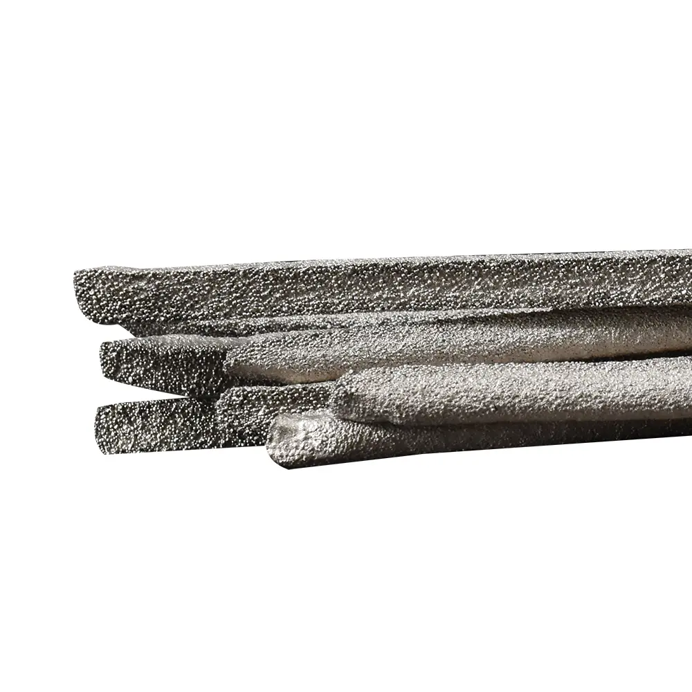

Nickel-based composite hardfacing rod is a composite hardfacing material featuring a nickel-based alloy matrix with tungsten carbide (WC) as the reinforcing phase, specifically engineered for surface strengthening of steel tools under extreme working conditions. Its core function is to form a crack-free, high-density wear-resistant coating on tool surfaces through welding processes, effectively addressing the rapid wear issues of conventional tools in high-impact and high-corrosion environments.
Unlike ordinary welding rods, our formula precisely controls the particle size distribution of WC (60-80 mesh large particles + 200-300 mesh fine particles) and the wetting property of nickel-based alloy, ensuring no pores or cracks after welding.
Excellent weldability:
- Applicable process: can be oxygen acetylene flame welding; no resin binder, good welding flow under low flame temperature.
- Welding effect: no bubbles, no gas release, smooth and dense welding layer.
Chemical Composition
| Ingredient | Proportion | Act on | Collaboration |
| tungsten carbide (WC) | 60% | Large particles (100-200μm): resist abrasive wear during hard rock cutting; fine particles (20-50μm): fill matrix gaps and prevent crack propagation. | Large particles “skeletal support” + fine particles “matrix reinforcement”, forming a gradient wear-resistant structure, to avoid the single particle size caused by stress concentration. |
| nickel-base alloy | 40% | As a matrix, it provides excellent high-temperature corrosion resistance and ensures the bonding strength between the weld layer and the steel body. | The nickel matrix forms an “interlocking structure” with the steel body through metallurgical bonding, and the welding strength is more than 350MPa to avoid the peeling of the welding layer. |
Specification
| Grade | Shape | Size |
| 3BD60 | Rod | Φ6.3*545 |
If customization is required, the mixing ratio and relevant parameters must be provided.
Matters need attention
Pre-treatment before welding
The surface of the base material must be cleaned of oil (wiped with acetone) and oxide scale (sandblasted to Sa2.5 grade); otherwise, pores may form.
Preheating:
Select appropriate preheating temperature based on the base material type and workpiece size. Typically, preheat to 250-350°C, with inter-layer temperature at 250°C for overlay welding, and maximum inter-layer temperature not exceeding 500°C. For example:
- Low-carbon steel base material (e.g., 42CrMo): preheat to 220–350°C and hold at this temperature for 1 hour.
- High-alloy steel base material (e.g., 13Cr): Preheat to 300–400°C to prevent crack formation due to martensitic phase transformation.
Postweld treatment
Wrap with Ceramic Fiber Blanket (or Asbestos-Free Insulation Blanket) to control the cooling rate and avoid tissue brittleness.
If surface pores (diameter>0.5mm) are found, they should be polished with an angle grinder and then welded. The welding area should cover twice the width of the original welding layer.
Safe guarding
Wear heat-resistant gloves (>600℃) and welding face masks (with auto-adjusting light lenses). Ensure workshop ventilation of ≥5 times per hour.
Application Scenarios
Petroleum and natural gas industry: Horizontal well centralizer: solves the “adhesive sliding wear” between the centralizer and the well wall in the horizontal well of shale gas. After the application of a certain oil field, the drilling length of a single trip is increased to 2000 meters (originally 800 meters).
Horizontal well centralizer: solves the “adhesive sliding wear” between the centralizer and the well wall in the horizontal well of shale gas. After the application of the oil field, the drilling length of a single trip is increased to 2000 meters (originally 800 meters).
Mining machinery: the overlay welding of ball mill liners is better than high chromium cast iron (Cr28) in wear resistance, and the service life is doubled.
Cement equipment: the surface of the vertical mill grinding roller is strengthened to solve the composite failure problem of “erosion wear + adhesion wear” during clinker grinding.
Ocean engineering: the scour resistance coating of the submarine pipeline connector, corrosion resistance rate <0.05mm/ year.
Note: The above statistics are under typical working conditions. The actual effect is affected by lithology, drilling parameters, field environment, and operation specifications.